Modified:2021-01-18
Goal
The mission: integrate a bluetooth Apt-X Low Latency receiver into an AM/FM portable radio to use for watching TV (with a matching Apt-X Low Latency Transmitter); do it in a few hours of effort using on-hand materials.
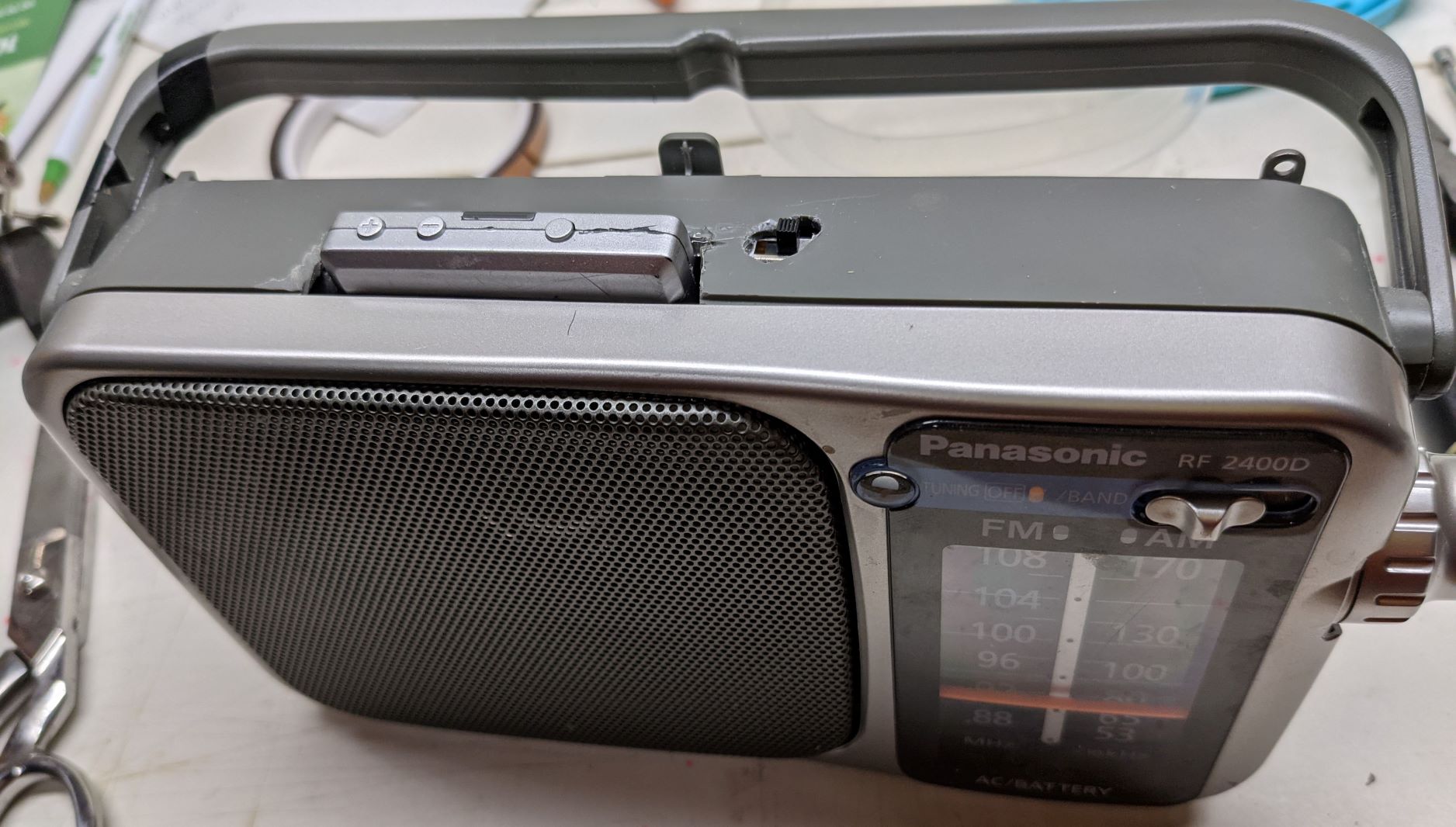
I have a Panasonic RF-2400D (I may earn a small commission from this link, thanks!), which is a fabulously simple audio device - it receives AM and FM radio. I wanted to use this for higher-quality audio that a pretty terrible portable Bluetooth speaker I had been using for watching TV. The proposal was to integrate a Bluetooth Apt-X Low Latency receiver (BT-Rx) into this radio.
A few problems needed to be solved:
- Find the line-out audio signal from the RF processing chip
- Engineer a solution to multiplex the AM/FM signal and the line-out from the BT Rx to the audio amplifier.
- Combine stereo output from Bluetooth to mono
- Adapt the existing power sources to permanently power the BTRx
- Physically mount the BTRx
In short, all these things were done, although the power adaption took a few tries.
If you’re following along at home and want to try something similar, I highly recommend the following soldering station. I have been through several varieties from Radio Shack irons, cheap-from-Aliexpress ones, but none has even been close to ease-of-use and quality. Check it out in the supplies list.
Supplies:
- Panasonic RF-2400D (I may earn a small commission from this link, thanks!)
- Bluetooth Apt-X Low Latency Receiver (I may earn a small commission from this link, thanks!)
- X-Tronic Model 3020-XTS Digital Display Soldering Iron Station (I may earn a small commission from this link). Highly recommended!
- Buck Converter (I may earn a small commission on this link purchase)
- 3.5mm stereo plug
- SPDT Slide switch
- Connectors, as desired, for battery to bluetooth receiver
- Various wire
- Resistors (see below for details)
Stereo to Mono
I had a spare 3.5mm plug. To this, I used two 470 ohm resistors on each channel, attached together to form the single output signal from the BTRx. For more details, see examples, such as at: https://www.instructables.com/Simple-Way-to-Convert-Stereo-to-Mono/
Audio Signal Multiplexing
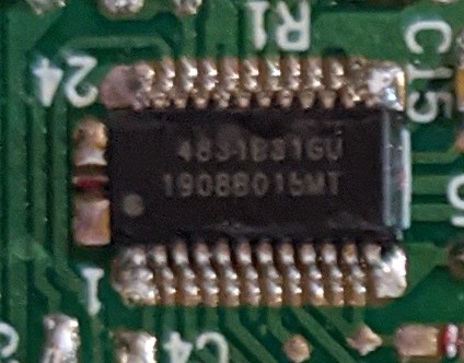
I’ll skip right to the good part.. investigating the circuit board. The heart of the RF audio processing seems to be a Silicon Labs am/fm series chip. While I couldn’t parse the chip markings exactly, the chip pinout and function seem very close to Si4831 https://www.silabs.com/documents/public/data-sheets/Si4831-35-B30.pdf
Other links:
https://www.silabs.com/support/resources.p-audio-and-radio_multi-band-radios_si4820-24-25-31-35-36
Looking at the spec sheet, the two channels of audio output are pins 23 and 24. These signals trace through SMD resistors and combine similar to the 3.5mm plug above. Further tracing shows this signal enters the volume potentiometer. Bingo.
The plan is to:
- cut the trace of this mono-signal from the Si chip,
- attach wire to original trace and to a switched terminal of a SPDT slide switch.
- Attach BTRx output to other switched terminal
- Attach wire from common terminal of SPDT to volume potentiometer.

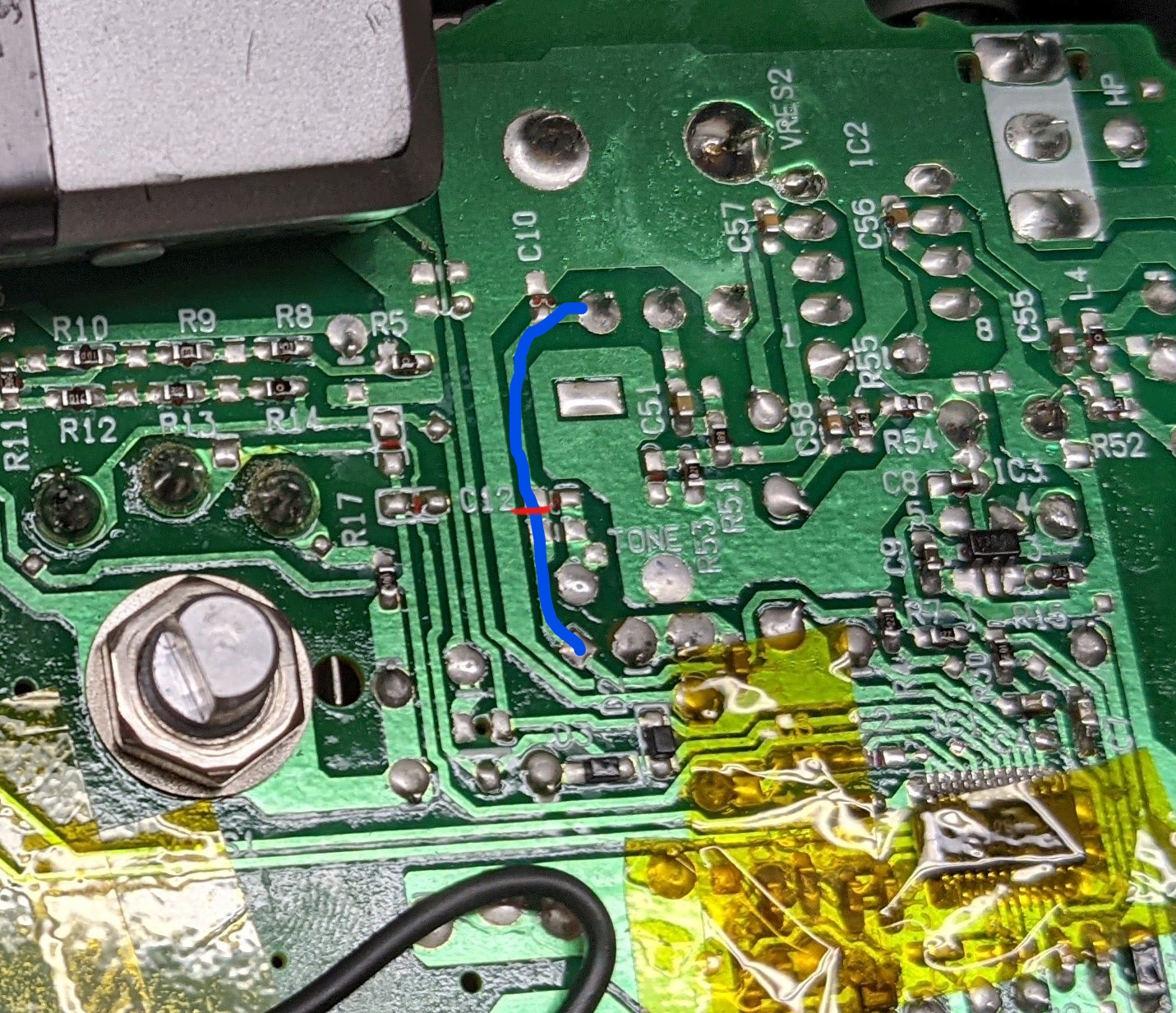
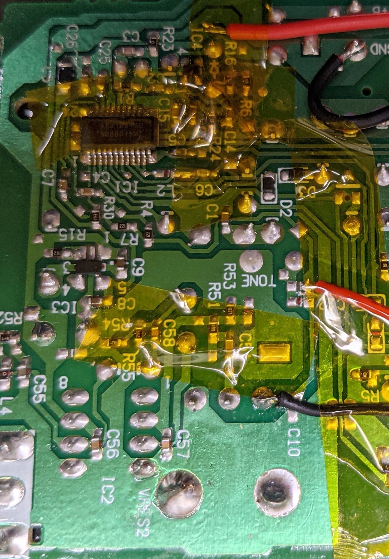
In the photo below, the PCB trace in blue is the original audio signal from RF IC to volume potentiometer. the small red line is where I cut the PCB with a hobby (Xacto) knife. The next photo shows the wires soldered on that lead to the switch.
Power Source
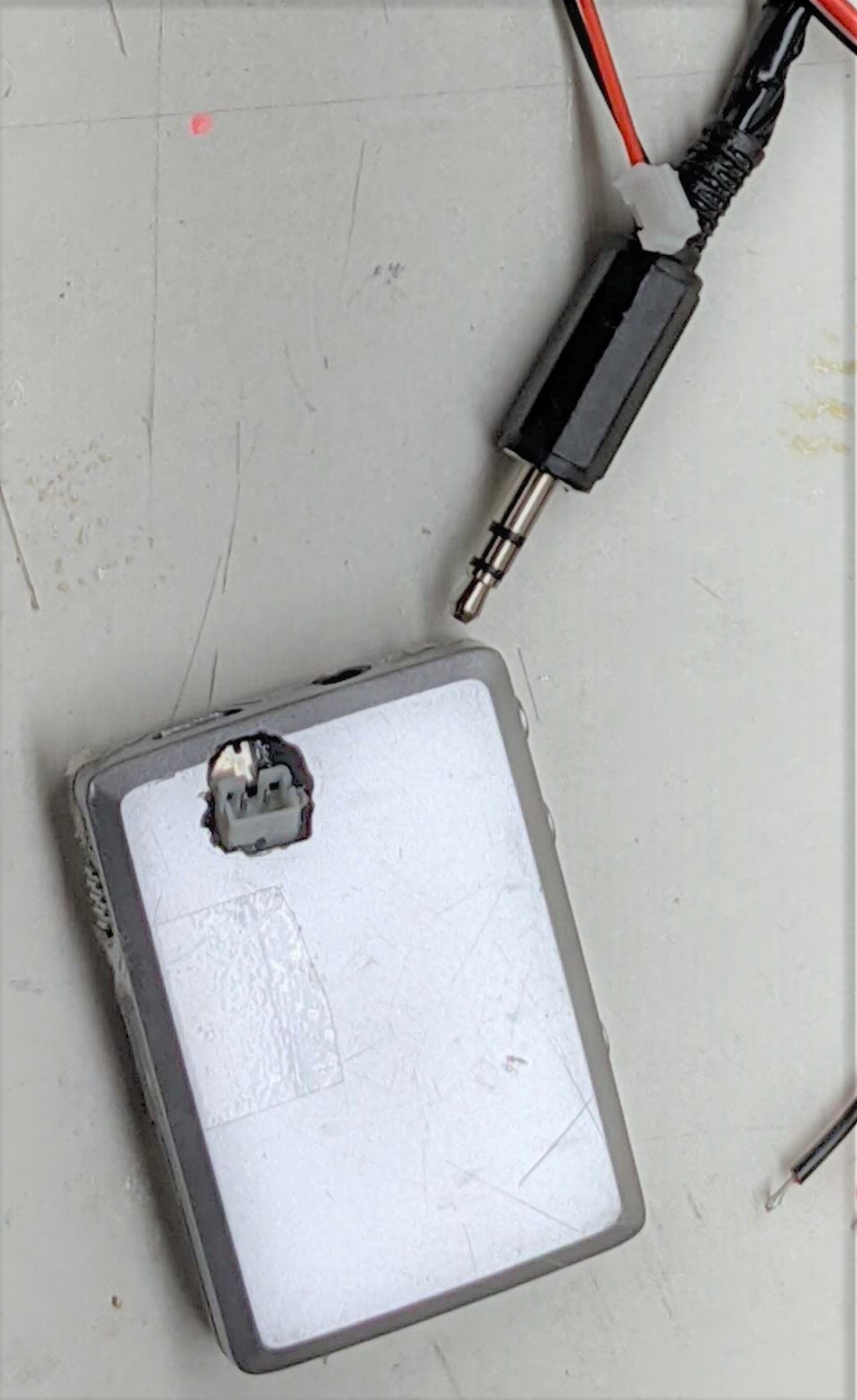
The original power of the BTRx was a 300-ish mAh lipo battery. It quickly wore out, and I hacked another battery in its place, but added a 2-pin connector for easier future replacement. This modification probably deserves another post with the details. I leveraged this connector to easily power the BTRx from the Panasonic radio’s source, which is ultimately 4 AA batteries (I use rechargeable NiMH).
I first tried to tie into the regulated power used for the RF IC, and did. However, it turns out the voltage was just under the threshold the BTRx used to determine “low battery”, so periodically, I got low battery warning sounds. Annoying.
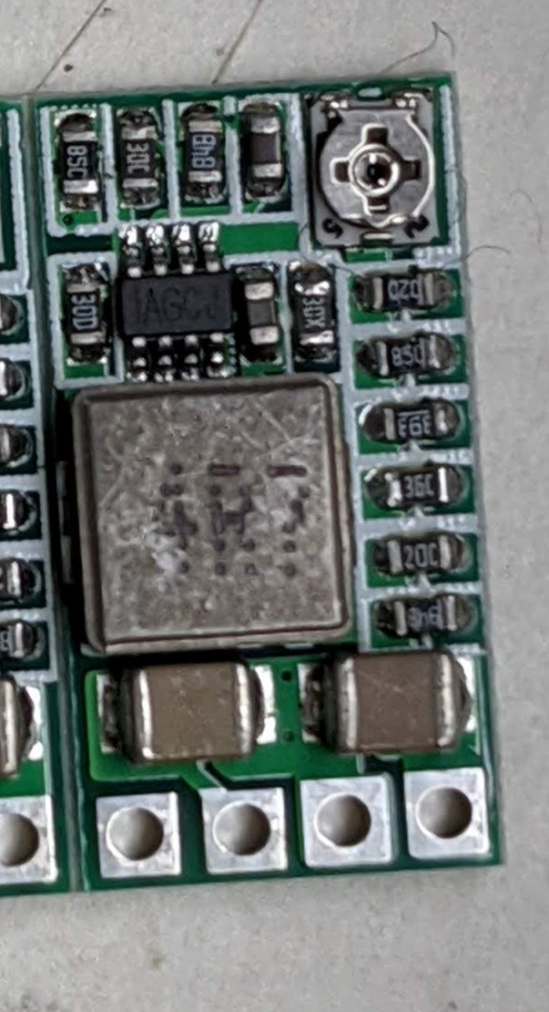
The second attempt was to use an adjustable buck voltage regulator. I had one laying around, which are available for less than 1 USD at various online stores. If you want to try, these seem like they would work well: Buck Converter (I may earn a small commission on this link purchase).
I adjusted it to output 4v. For reference, the input is about 5.2v with 4 NiMH rechargables powering the radio, which may have worked directly to the BTRx, but I didn’t want to risk overvolting it’s regulator. I wired this up to the switched power pins at the physical “OFF/FM/AM” switch.
The images below shows the 2-pin connector added to the BTRx, and the voltage regulator. Sadly, I didn’t get photos of the final interior installation of this second attempt.
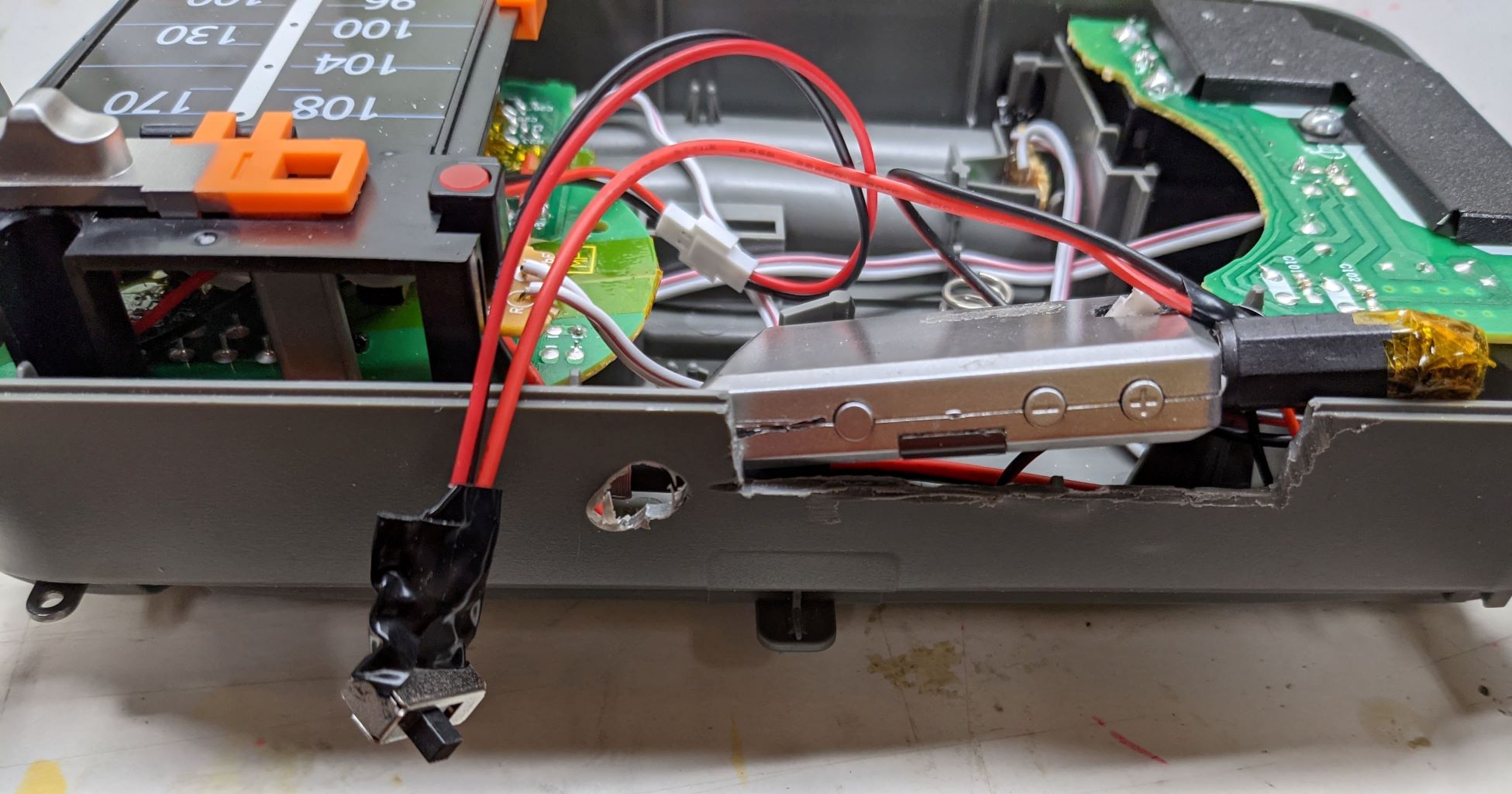
Mounting
For a quick ‘n’ dirty hack, I simply cut out a slot at the top of the radio case to gain access to the BTRx buttons (which is required for bluetooth pairing and volume). Another hole was cut, very very roughly, for the switch that selects between radio and bluetooth signals. The speaker is quite large and bulky (I did say I wanted a nice clear sound), but there was barely enough space to squeeze this in. Super Glue (cyanoacrylate) gel worked well to secure it to the case.
Operation
The radio works wonderfully! The battery life is much better than the originals, which was separate BTRx and portable speaker. The sound is much better, too. And ultimately, I didn’t pay anything extra for this project :-) Thank me later, landfills and ocean.
Other possible hacks
Note, that the RF IC and the PCB seem to have support for “Tone”. One possibility is to add bass and treble controls.